Category Archives: F-100

Side Steps and a Nose Job

Haven’t updated the site for ages, but I’ve still been working away on the truck as often as I can. The running boards I got with the truck were completely rotten so I plasma’d the tops off them, screwed them to the workbench (well the kitchen worktop on two trestles that doubles as a workbench!) and cut new tops out of sheet metal. They were a good lesson on not welding too much at once or you’ll warp it… Which I did. So after cutting it back out and straightening it I took a bit more care. I also made new supports for them as the originals hang below the boards at the back, and they’ll just hit stuff. With some hidden fixings added I gave them a quick coat of primer to keep the rust at bay for a bit and put them on the "to do" pile.
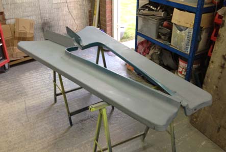
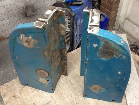
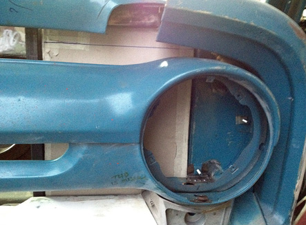
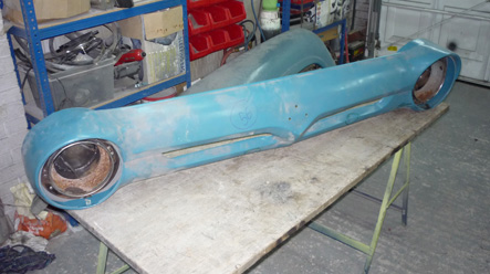
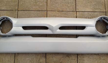
I was also concerned about the nose and the gravel pan, as they both had been worked on and were starting to rust. The nose was dented and twisted all over, and had some bad pitting where the emblem sat, and as I didn’t want the emblem on there anyway, I cut it out, shaped it flat and made a new piece.
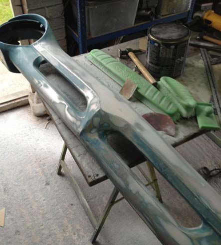
Doesn’t sound like much when you say it quickly, but it took hours to get them straight. A quick coat of primer to seal them up, and they too went on the to do pile.
Hood Sliders Made

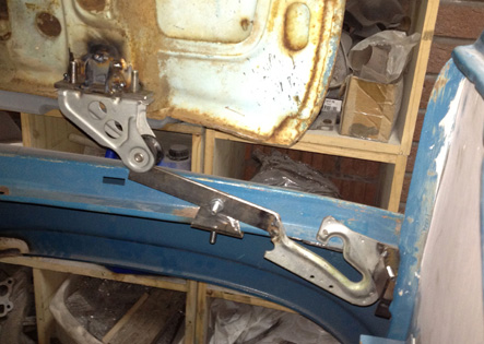
With the hood hung back on, it was time to make the guides to save the wings taking a beating as you closed the hood and hold the back of it down when you’re driving!. I bought a set of guides and wheels from a BMW and set about getting them roughly where I thought it should sit. The wheel part was relatively easy, as I just notched the crossmember where the hinges mounted and tacked a piece of flat bar into place. The guides themselves turned out to be a lot tougher. The length of the arms that I made were obviously completely different to the BMW ones, and this left me with too much movement from front to back for the short guides. I tacked on some flat bar at the front to make up for this, and then set about trying to get the angle and alignment right.

After crushing my fingers a million times, and it popping the clamps off as it slid, I bit the bullet and tacked it together temporarily. It sorta worked, but just wasn’t right. At this point I gave up for the evening to have a think about it all. After thinking about it all week, I decided the best option was to make it all as adjustable as I could. I cut it all off and made some brackets that mounted on existing holes in the wings, and slotted the holes so I could move it all about. Happy that it would hopefully work, I made another set for the other side and bolted it all together before climbing inside and adjusting it all to line up as I watched it. After a couple more tweaks to the brackets, it all works pretty much as it should. The sliders are seriously ugly tho, so I’ll draw them out and get a couple of pairs lasered (I’ll do the same to the C10 when and if I ever get on to it!).

Hood back on and Adjusted

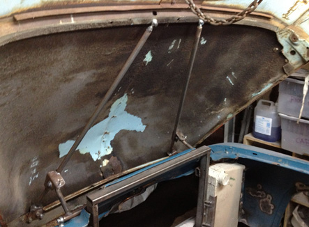
I had spent ages making a reverse tilt hood mechanism as I didn’t have the original hinges, and thought it would be a good idea. Happy with it all I’d taken it back off and stuck the hood in the shed ready for the day when I’d be working on it. In the meantime I re-made the core support it all sat on so I thought I’d better re-fit it and check it still worked, and add some rollers and guides for the firewall edge of it. I got all the brackets back on, dropped the hood on, and climbed under the wheel arch and over the frame to get inside and bolt it all up. It was out by a mile. I spent the next few hours adjusting the arm lengths (it’s all rose jointed) and checking it all before I decided that it was never going to fit. I had to cut some of the core support cover so that the arms didn’t fold against them, and then extend the arms slightly so that the rose joints were not right at the very end of the thread. With it all done, it sits pretty nicely but is out about a centimetre or so when the hood is open.

I couldn’t open the door to look at it all properly as it was pouring with rain, so I’ll have to hope for a dry day next weekend and have a measure of it all to check. I have the guide plates and wheels off a 3 series BMW reverse bonnet to put on there to guide the hood in, which should also save my fingers being crushed hopefully!

Intercooler Mountings

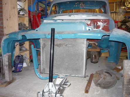
I needed to come up with a way of holding the intercoolers in place, whilst still letting plenty of air through them. I decided that I’d re-shape the wind deflector panels around the intercoolers to hold them in place on the one side. I’d already bent one into shape, so re-bent it with a lip at the back and test fitted it. I was happy with how it came out, so I made a tunnel for the wing edge to slot into, and made new lips for the top edge to hold it all rigid. Happy with how it all looked, I did the other side and filled in the original mounting holes for the nose.

With that done, I needed to come up with a way of holding the other side in place. I settled on some bits of box section and angle bolted to the core support which should be plenty strong enough. When I actually get around to painting it I’ll put some foam pads on the mounting surfaces to clamp it all in without squishing it. Hard to see in the pic, but it’s held both sides and there is a bracket to hold it up at the bottom too. I guess the only way it could move is upward when i go over a bump, but I’ll put some foam in and see if I need a top bracket.

’56 Nose Fitted

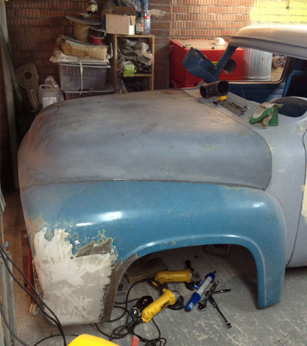
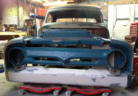
I don’t like the ’55 nose as much as the ’56 nose, and as I had both I decided on the ’56. The mounting tabs are in different positions to the ’55 and half the mounts would be in the intercoolers with my new setups. I’d cut them off and moved them previously so now needed to get it mocked up and drill new holes in what was left of the wind deflector panels. I had a massive clear up in the garage, and slid the truck over sideways on the dollies so that I could get to both sides (and my workbench finally!) and set about putting the front on again. I’d re-made the core support since I last had it all together, so was expecting to have to tweak it all to fit again. It was pretty close, but just needed a tiny tweak on the one side to get it all lined up. With the wings hung, and the core support cover in place it was slightly further out than I thought, so I bolted the gravel pan in too and tightened it all up before cutting trough a few tacks and moving the support on the passenger side. With that all done, I bolted in the side lights and clamped the nose in place before measuring all the gaps. With a bit more moving around, I was happy with the position of it all so broke out the drill.

It took a fair bit of measuring and moving to get it all lined up and back together, which was a pain in the ass as it’s only a foot or so from the garage door which has a C10 stopping it from opening….. I gave up in the end and dragged it diagonally in front of the other door and got the last few bolts drilled and fitted. Really happy with how it all looks, can’t wait to put it all together properly.

’56 Nose on a ’55 Front

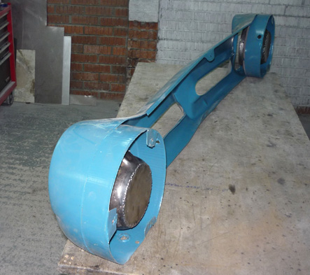
I’d decided to fit the ’56 nose that I had instead of the original ’55 one. Both were in pretty poor shape, so it was a lot of work either way. I marked up all the dents, and put it against a flat surface to see how badly it was twisted. Pretty badly was the answer. After a fair bit of bending and twisting I was happy with the way it sat, so took out all the dents. There were lots of holes for grommets etc that I’d rather move to other places, so I filled these in while I was at it. The nose mounts flush against the wind deflector panels, and on a ’55 the headlights stick out. On a ’56 the headlights are recessed, and there is a recess in the deflector for them to sit in. As the intercoolers needed to go where the recess was, i needed a plan ‘B’.

I bought new headlamps with LED sidelights which are quite shallow, and after some measuring decided I could cut the backs of the buckets flush and still have enough room for the wiring. Some careful cutting and welding later (and some time in my latest toy from eBay, a shot blast cabinet) and they were done. Happy with it all, I took them back apart and gave them a coat of rattle can primer before carrying on with the nose. The tabs are in a different position on the ’56 nose compared to the ’55 nose, and only half of the mounting holes are available with the intercoolers in, so i carefully cut off the tabs and made new ones for both sides. Should be fun mounting that by eye!

Trans Tunnel Made

I finally got round to ordering some sheet steel to make the trans tunnel and a few other bits. So with two sheets of 0.9mm at the ready, I set about it. I planned to make a square-ish tunnel as it would be relatively easy to do so folded one up out of cardboard before commiting to metal. With it sat in place, I hated it. More cardboard later, I had one that was angular that I thought would look good and started to fold it up out of steel. Not long into it, I decided I didn’t like that either so that became a pile of spare for patches. At this point I’ve had enough, so decide to close off the edges and make a cone to cover the top. With the big ruler screwed to the bench, I drew out a few cones and picked the one I liked the best. With it cut out of steel, I gently formed it over my leg and the edge of the bench with my hands. It came out really well, so I drilled some holes and cleco’d it to the closeout panels.

I then spent ages trying to get the shape of the top half of the cone plus the tab in one piece. In the end I gave up as the jaw of the shrinker wasn’t deep enough and made the tab with a flange to weld onto the top cone. A few hours of messing about with cardboard and I had the top cone cut out of metal and the whole lot cleco’d together. After marking where it all overlapped, I hammered a small lip on the edge of the cone to make it rigid before re-assembling and putting a few tacks on. A few tweaks, and I set about welding it together with the MIG as I was too lazy to set the TIG up. It all ended up solid, but not the prettiest bit of welding I’ve ever done. It’ll be under a carpet so it’s hardly the end of the world! A few screws to replace the two cleco’s that held it in place and called it a day for now till I can cut the other side of the firewall to suit.

Core Support Crossmember Build

As the first piece of the new crossmember took me ages to cut out with a grinder, I decided to splash out on a double mitre saw to do the rest. After measuring for the drop on the other side, I set the saw and cut up a block of wood as a test. It was pretty much spot on, so I cut up a piece of box section. I still had to cut the notch out with the grinder, but it was still a million times easier. I measured down to my scrap guide, cut out the drop pieces and tacked them in. I cut it back off, moved it around a bit, trimmed it a bit and eventually got it to sit pretty much where I wanted it (the ends of the frame are different lengths it turned out).

With it all tacked in, I cut off the scrap guide. With another piece of 2×4 tacked in between the two, I had a crossmember again. Next up was the frame for the radiator itself which the slam panel sits on. I took the angles off the inside of the wings (they have panels that bolt across) and set the angle on the saw to match. A crossbar and a few tacks and it was a complete piece. The X5 radiator had mounting tabs on the top edge, so I ended up making a crossbar for them, which I’ll eventually use to mount the fans from too. I cut the slam panel in a few places to make it easier to work out where it all had to sit so I’ll have to repair that too. Nothing too major tho.

Core Support Crossmember Mockup

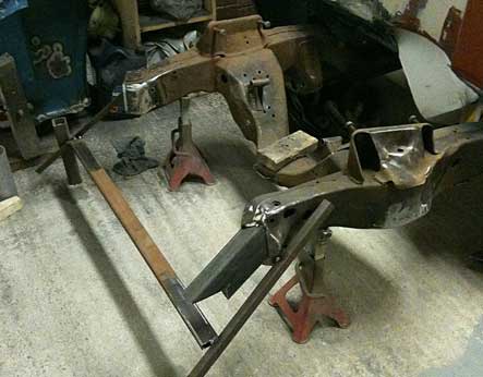
After throwing away the extremely wonky and crappy looking core support crossmember, it was time to make a new one. I got the frame back off its side, put the cab brackets on and dropped the cab in place. With that done, I levelled up the front of the chassis and hung the wings supported on wooden blocks. I then jacked the core support into position and moved it around till it all sat in the right place.

That gave me a position for the bottom of the core support so after lotsof measurements from different points on the frame I took it back out and got some scrap bits to make a guide. After hours of little adjustments followed by re-checking it all over again I was happy with the position. I tacked it all together so I had a reference to work off and had a cup of tea and a think. The ends of the frame were angled outwards (at different angles too), so after even more measurements I set about the 2×4 box section I’d bought to do this. Unfortunately the drop was too steep to do in one piece (I would have had to box the tops and bottoms of the angle) so that one went in the scrap box and plan B was formed. This was to notch out the end for a piece of straight box section to drop down. With it tacked in place, it was time to call it a day. Pretty pleased with it all.

Few more Bits and Bobs on the Frame

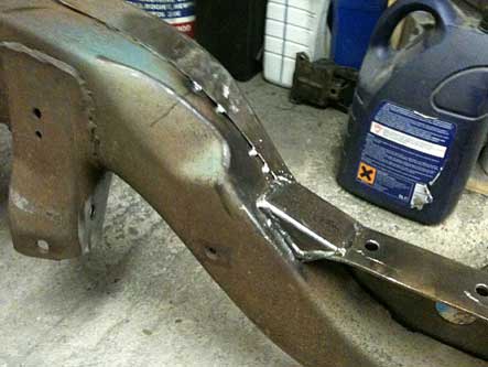
I didn’t like the way the top of the old frame had been joined into the Camaro clip, it had been cut too short by the look of it and hammered down until it touched the clip. It didn’t look the strongest of joins to say the least. A couple of quick cardboard templates later, I cut out some pieces of box and welded them in place.

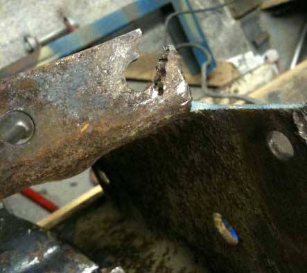
Next on the list was to repair the outriggers ready to put them back in place. They had been hacked about when they put the clip on as well, so I’d taken them off to straighten them out and repair the holes.

A little work with some scrap and the gas torch and they were as good as a fifty year old bracket gets I suppose!

IMG_0120