Category Archives: Chassis

Core Support Crossmember Build

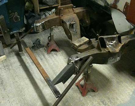
As the first piece of the new crossmember took me ages to cut out with a grinder, I decided to splash out on a double mitre saw to do the rest. After measuring for the drop on the other side, I set the saw and cut up a block of wood as a test. It was pretty much spot on, so I cut up a piece of box section. I still had to cut the notch out with the grinder, but it was still a million times easier. I measured down to my scrap guide, cut out the drop pieces and tacked them in. I cut it back off, moved it around a bit, trimmed it a bit and eventually got it to sit pretty much where I wanted it (the ends of the frame are different lengths it turned out).

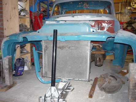
With it all tacked in, I cut off the scrap guide. With another piece of 2×4 tacked in between the two, I had a crossmember again. Next up was the frame for the radiator itself which the slam panel sits on. I took the angles off the inside of the wings (they have panels that bolt across) and set the angle on the saw to match. A crossbar and a few tacks and it was a complete piece. The X5 radiator had mounting tabs on the top edge, so I ended up making a crossbar for them, which I’ll eventually use to mount the fans from too. I cut the slam panel in a few places to make it easier to work out where it all had to sit so I’ll have to repair that too. Nothing too major tho.

Core Support Crossmember Mockup

After throwing away the extremely wonky and crappy looking core support crossmember, it was time to make a new one. I got the frame back off its side, put the cab brackets on and dropped the cab in place. With that done, I levelled up the front of the chassis and hung the wings supported on wooden blocks. I then jacked the core support into position and moved it around till it all sat in the right place.

That gave me a position for the bottom of the core support so after lotsof measurements from different points on the frame I took it back out and got some scrap bits to make a guide. After hours of little adjustments followed by re-checking it all over again I was happy with the position. I tacked it all together so I had a reference to work off and had a cup of tea and a think. The ends of the frame were angled outwards (at different angles too), so after even more measurements I set about the 2×4 box section I’d bought to do this. Unfortunately the drop was too steep to do in one piece (I would have had to box the tops and bottoms of the angle) so that one went in the scrap box and plan B was formed. This was to notch out the end for a piece of straight box section to drop down. With it tacked in place, it was time to call it a day. Pretty pleased with it all.

Few more Bits and Bobs on the Frame

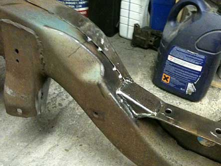
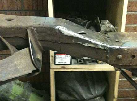
I didn’t like the way the top of the old frame had been joined into the Camaro clip, it had been cut too short by the look of it and hammered down until it touched the clip. It didn’t look the strongest of joins to say the least. A couple of quick cardboard templates later, I cut out some pieces of box and welded them in place.

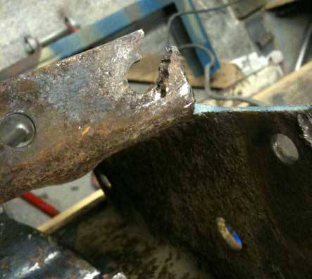
Next on the list was to repair the outriggers ready to put them back in place. They had been hacked about when they put the clip on as well, so I’d taken them off to straighten them out and repair the holes.

A little work with some scrap and the gas torch and they were as good as a fifty year old bracket gets I suppose!

IMG_0120

Re-Shaping the Brake Bracket

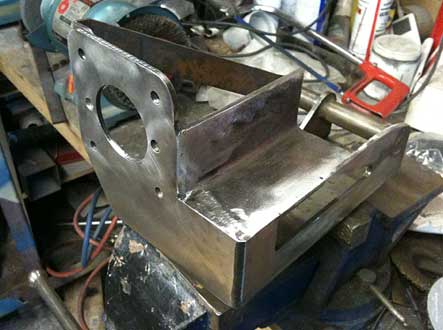
I bought a brake pedal and bracket to fit a standard booster off ebay a while ago. The Camaro frame was in the way of bolting it in as it should, so I trimmed it till it would fit and then set about strengthening it again. I cut a piece of angle to fit and then welded it in place.

I don’t intend running a booster, so I drilled the bracket to fit a Wilwood manual master while I was at it. Not sure about how I’ll fix it to the frame yet as the bottom mount is covered by the Camaro frame. Maybe a long bolt, or just weld it in and call it a day.

Making space for Air

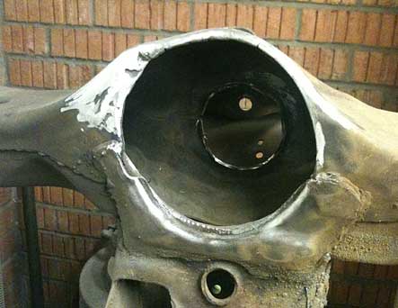
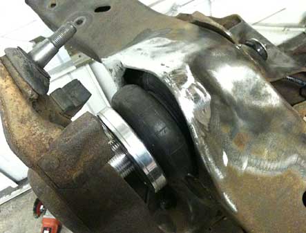
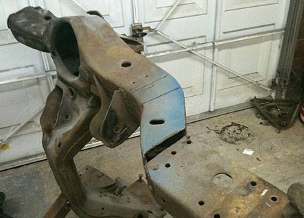
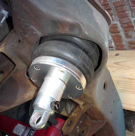
With the frame on its side to work on, I could get to work on the spring pockets. I put the lower A arm back on temporarily, and bolted the Shockwave front shock to it. They were too wide for the pocket, so I cut all the way round the outer edge and folded it all back until they had a decent amount of space around them. Unfortunately I found the top spring retaining ring hit the top of the shock, so I had to open that up as well to give it some clearance. I’m sure it would have been an easy job with a plasma cutter or something, but it was hard work with a grinder and a die cutter. Nobody will ever see it apart from this pic, but I still did the best I could with it.

With that done, I inflated the shock with the air line and checked I still had enough clearance. It was a bit tight in places, so I opened it up a bit further then welded all the cuts up and smoothed them off. With one final test fit and inflation I was happy it would all be OK and pulled it all back to bits again, and turned the frame over. The re-shape of the transition and the pocket on the other side took half the time as I knew what I wanted to do and that was another job done.

Making a Start on the Frame

I had decided that I should leave the bodywork alone for a while till it’s all back together and can be worked on properly, so it was time to look at the frame. I hated the way the front clip stuck out of the frame rails and wanted to blend it in properly. Before I went too far I double checked that it was straight as the piece I chopped off the front was so bad but luckily it was correct. I welded a piece of box section to the crossmember to hold it up on it’s side, and supported the other end with wood and set to work.

I marked up where I wanted the bend to start, then marked up the pie cuts and sliced them out with a thin blade. I put G clamps on the end, then heated the lined I’d marked with the acetalene torch until it glowed then tightened up the clamps until it was bent into position. Once it was cooled down I pulled off the clamps and tacked it in, then cut up one of the pie shaped pieces to fit in the gap between the rails. With it all finish welded and ground down it looked a million times better, and hopefully a bit stronger too.


Air Ride

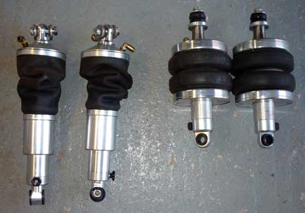
I spotted a second hand Air Ride setup for sale on the NSRA website, and it turned out to be the guy who I bought the wheels for the ’55 off. A week or so later, and two large boxes arrived at work for me. It was all as it had been pulled off the car, so it was covered in muck and looked a bit of a mess. I spent a few hours cleaning it all up, then temporarily plumbed it all together for a test. With the wiring setup to run off a battery, I turned it all on. It buzzed away for a few minutes, then had a go of the switches and both sets started to move about as you’d expect.

Bags.jpg

It was all new to me, and I thought it was really cool. I guess I need to get out of the house more!. Happy that it all worked as it should, I pulled it all back to bits, cling wrapped everything but the shocks and put it all back away. The mountings were swapped front to back for what I wanted, so I pulled both sets to pieces, and put them back together with the different tops on. A quick test of how they look in the frame before they got packed away too. Wont need them for a long time yet, but one more tick off my wishlist of bits.

Baggins.jpg

Gearbox Crossmember

With the motor sat on it’s mounts, I needed to sort the gearbox mount out so that it wasnt balanced on a piece of angle iron wedged under there. It also needs to be able to move backward for the 4L80-E so after a lot of lying under there and looking at it I decided to make the mount sit on top of the old Camaro rails and bolt through as this would give me the most room for an exhaust.

Crossmember

My mate John had given me some box section to make it out of, and I set about making the centre section and working back. The mount bolt is not long enough to go through the 2×1″ box section I was using, so I decided to copy the OEM mount and cut a hole big enough for a socket to go in on the bottom. With that done, I worked out the angle for the 2×2″ box and hacksawed it to fit. After the fourth cut I was wishing I had space for a bandsaw in the garage. I tacked it together, then made the two 2×1 arms and bolted it all in place and jacked it up till I had the gearbox where I wanted it on the level. I could then measure up for the two “feet” and after a quick test fit seam welded everything then cut all the ends to match the angles of the uprights. No one will see it, but I want it to look OK. Not much to it really but I’m pleased with my self.

Gearbox Crossmember

Engine Mounts Done

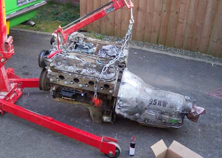
I wanted to get the engine mounted properly and work out how much of the firewall needed removing to get it to fit. I decided to just cut a big square out of it and re-make it later as the existing bulge was too far down to use. I have a spare 4L60-E with a snapped off tailshaft housing so I bolted that on to the block to hold the back of the engine up when it’s on proper mounts. With that done, I hung it roughly in position on the crane and started measuring. With the tailshaft dead centre between the rails, the engine looked visually off centre and I just could not get it to sit right.

Motor-and-Box.jpg

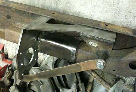
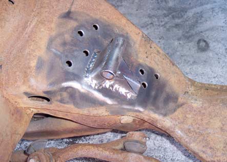
I ended up with it sat as close as I could without cutting the sump or crossmember, and cut pieces of box section and some tube to fit. I dropped it onto the new mounts, checked everything again and after a bit of shaping was happy. I scraped around the edges so that I could put them back in the same place and lifted it back off the mounts. With some supports welded on, I dropped it back into position then tacked them in place. Next day the engine came back out, and I welded them in all the way around. I also realised that it looked so bad visually as the core support crossmember was way out of line. It was nearly an inch out horizontally and vertically, so I cut off the one side and carefully lined it all back up before welding it in again. The motor then went back in and all the front sheetmetal on and I was done for the day. At worst I may have to slot the core support holes to get it all to fit, but at least its straight now.

Engine-Mount.jpg